(Scope of Work) สำหรับการบำรุงรักษาเชิงป้องกัน (Preventive Maintenance) และการปรับปรุงอุปกรณ์ในระบบ Active Power Filter (APF) และ Static VAR Generator (SVG)

ขอบเขตงาน (Scope of Work) สำหรับการบำรุงรักษาเชิงป้องกัน (Preventive Maintenance) และการปรับปรุงอุปกรณ์ในระบบ Active Power Filter (APF) และ Static VAR Generator (SVG) ของแบรนด์ DELTA:


ขั้นตอนการดำเนินงาน:

  1. วิเคราะห์คุณภาพพลังงาน (Power Quality):
    • ทำการวัดค่า Power Quality ด้วยอุปกรณ์ Class A ทั้งก่อนและหลังการติดตั้งหรือเปลี่ยนอุปกรณ์ใหม่ เพื่อประเมินประสิทธิภาพของระบบ.
  2. ตรวจสอบความสะอาดและสภาพของตู้:
    • กำจัดฝุ่น สิ่งปนเปื้อน สนิม และการกัดกร่อนของโลหะในตู้ควบคุม.
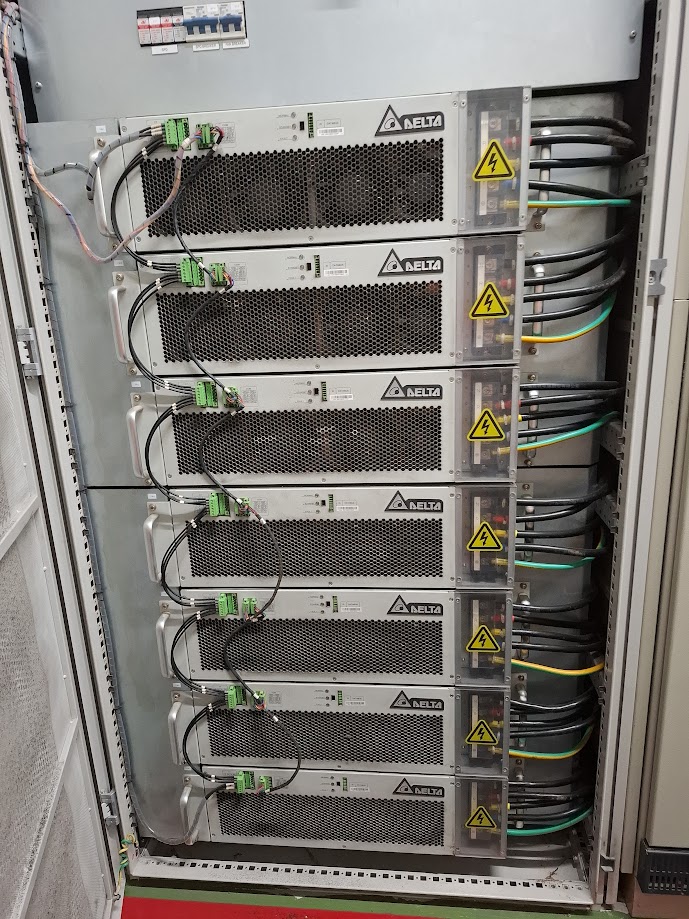
  3. ตรวจสอบสายไฟและการเชื่อมต่อ:
    • ตรวจสอบความเสียหายและความแน่นหนาของสายไฟฟ้าและสายควบคุม.
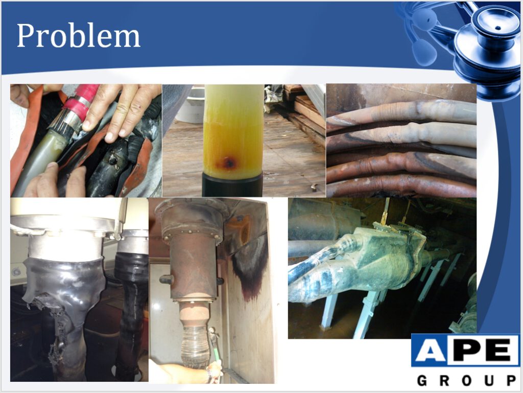
  4. ตรวจสอบฉนวนภายใน:
    • ยืนยันว่าไม่มีรอยแตกหรือเสียหายในฉนวนภายใน.
  5. ตรวจสอบการเชื่อมต่อสายดิน:
    • ตรวจสอบว่าสายดินของประตูและจุดเชื่อมต่อต่าง ๆ ถูกติดตั้งอย่างถูกต้อง.
  6. ตรวจสอบการขันสกรู:
    • ใช้ประแจที่มีการตั้งค่าแรงบิดที่แม่นยำในการขันให้แน่น.
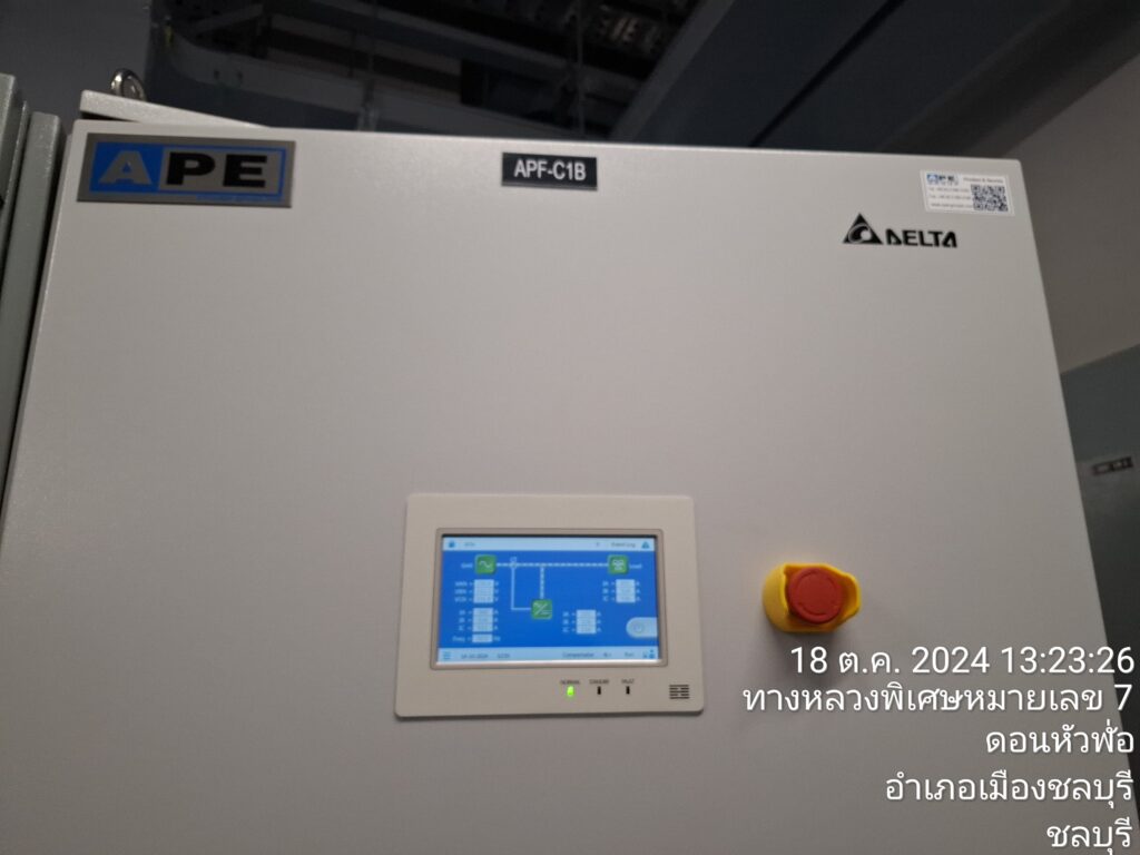
  7. ตรวจสอบแผง HMI:
    • ทดสอบฟังก์ชันและการตั้งค่าต่าง ๆ บนแผงควบคุม HMI.
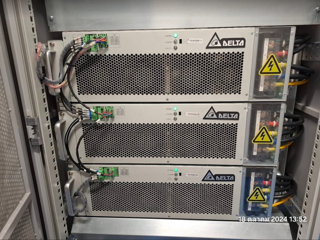
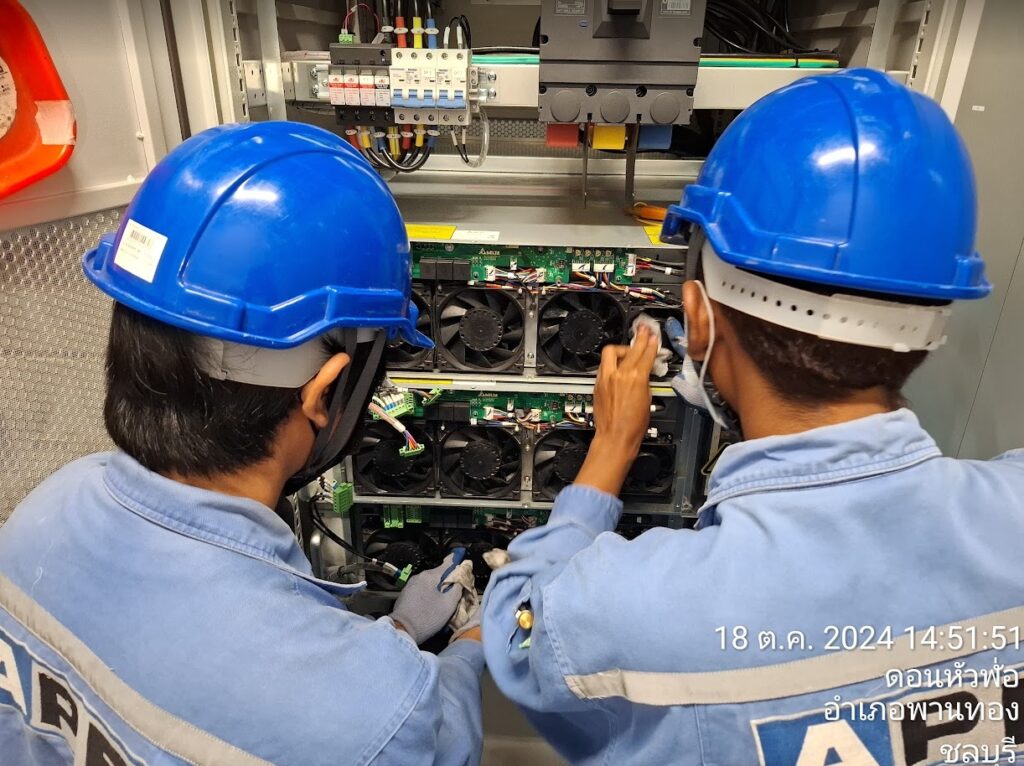
  8. ตรวจสอบพัดลมระบายความร้อน:
    • ตรวจสอบการทำงานของพัดลมระบายความร้อนในตู้ควบคุมและโมดูล.
  9. ตรวจสอบ DIP Switch:
    • ตรวจสอบการตั้งค่า ID ของ DIP Switch ในแต่ละโมดูลให้ถูกต้อง.
  10. ตรวจสอบฟังก์ชันของ Circuit Breaker:
    • ทดสอบการทำงานของเบรกเกอร์วงจรไฟฟ้า.
  11. ตรวจสอบข้อความผิดพลาดและบันทึกเหตุการณ์:
    • ตรวจสอบข้อความแจ้งข้อผิดพลาดและข้อมูลใน Log Event เพื่อระบุปัญหา.
  12. ตรวจสอบการทำงานของอุปกรณ์ทั้งหมด:
    • ตรวจสอบว่าอุปกรณ์ทุกชิ้นทำงานได้ตามปกติ.
  13. วิเคราะห์คุณภาพพลังงานอีกครั้ง:
    • ทำการวัดค่า Power Quality หลังการติดตั้งและเปลี่ยนอุปกรณ์เพื่อยืนยันผลลัพธ์ที่ได้.

ประโยชน์จากการดำเนินงาน:

  • ปรับปรุงคุณภาพพลังงานในระบบ.
  • ลดความเสี่ยงจากความเสียหายหรือการทำงานผิดปกติ.
  • ยืดอายุการใช้งานอุปกรณ์ในระบบ.
  • เพิ่มความเสถียรและประสิทธิภาพของระบบไฟฟ้า.

หากต้องการคำแนะนำเพิ่มเติมเกี่ยวกับวิธีดำเนินงานในระบบ APF/SVG หรือการวิเคราะห์ Power Quality สามารถปรึกษาผู้เชี่ยวชาญด้านระบบไฟฟ้าเพิ่มเติมได้ครับ


แนะนำตัวอย่างแก้ปัญหา เกี่ยวกับค่า Power Factor ต่ำ:

สรุปและแนะนำเพิ่มเติมเกี่ยวกับการปรับปรุงค่า Power Factor

ปัญหา:
  • ค่า Power Factor ปัจจุบันต่ำกว่ามาตรฐาน (0.85) ขณะมอเตอร์ทำงานแบบโหลดไม่มีภาระ
  • ส่งผลให้ระบบไฟฟ้าไม่เสถียร และอาจเกิดการสูญเสียพลังงานไฟฟ้า

    แนวทางแก้ไข:
  • ติดตั้ง Capacitor Bank: ขนาดประมาณ 50 kVar แบ่งเป็น 2 ชุด ชุดละ 25 kVar
  • ตำแหน่งติดตั้ง: ชุด Starter Motor (ตาม Single line diagram for DB1)
  • วัตถุประสงค์: ชดเชยค่า Reactive Power เพื่อปรับปรุงค่า Power Factor ให้เข้าใกล้ 1

    ผลประโยชน์ที่คาดว่าจะได้รับ:
  • ระบบไฟฟ้าเสถียรมากขึ้น: ช่วยลดปัญหาการกระชากกระแสไฟฟ้า และแรงดันไฟฟ้าตก
  • ประหยัดค่าไฟฟ้า: ลดการสูญเสียพลังงานในระบบ
  • เพิ่มอายุการใช้งานอุปกรณ์ไฟฟ้า: เนื่องจากอุปกรณ์ทำงานในสภาวะที่เหมาะสมมากขึ้น

    ข้อควรพิจารณาเพิ่มเติม:
  • การคำนวณขนาด Capacitor: ควรให้ผู้เชี่ยวชาญด้านไฟฟ้าคำนวณขนาด Capacitor ที่เหมาะสมอย่างละเอียด เพื่อให้ได้ค่า Power Factor ที่ต้องการ
  • การติดตั้ง: ควรติดตั้งโดยช่างไฟฟ้าที่มีความชำนาญ เพื่อให้มั่นใจว่าการติดตั้งถูกต้องและปลอดภัย
  • การตรวจสอบและบำรุงรักษา: ควรมีการตรวจสอบ Capacitor Bank เป็นระยะ เพื่อให้แน่ใจว่าทำงานได้อย่างมีประสิทธิภาพ

    ข้อเสนอแนะ:
  • ศึกษาข้อมูลเพิ่มเติม: ศึกษาข้อมูลเกี่ยวกับ Capacitor Bank และการปรับปรุงค่า Power Factor อย่างละเอียด เพื่อให้เข้าใจหลักการทำงานและผลประโยชน์ที่จะได้รับ
  • ปรึกษาผู้เชี่ยวชาญ: ปรึกษาผู้เชี่ยวชาญด้านไฟฟ้า เพื่อขอคำแนะนำในการแก้ไขปัญหาและเลือกอุปกรณ์ที่เหมาะสม
  • ติดตามผล: หลังจากติดตั้ง Capacitor Bank แล้ว ควรมีการตรวจสอบค่า Power Factor เป็นระยะ เพื่อประเมินผลการปรับปรุง

    สรุป:
    การติดตั้ง Capacitor Bank เป็นวิธีการที่นิยมใช้ในการปรับปรุงค่า Power Factor และแก้ไขปัญหาที่เกิดจากค่า Power Factor ต่ำ การดำเนินการตามแนวทางที่แนะนำข้างต้น จะช่วยให้ระบบไฟฟ้าของคุณมีประสิทธิภาพมากขึ้น และประหยัดค่าใช้จ่ายในระยะยาว
    คำถามเพิ่มเติม:
  • ต้องการข้อมูลเพิ่มเติมเกี่ยวกับ Capacitor Bank หรือไม่?
  • ต้องการทราบขั้นตอนการติดตั้ง Capacitor Bank หรือไม่?
  • มีข้อสงสัยอื่นๆ เกี่ยวกับเรื่องนี้หรือไม่?
    หมายเหตุ: ข้อมูลข้างต้นเป็นเพียงแนวทางเบื้องต้น การตัดสินใจใดๆ ควรพิจารณาจากข้อมูลที่ครบถ้วนและปรึกษาผู้เชี่ยวชาญ

PM APF/SVG DELTA

Preventive Maintenance and equipment modification

Scope of work

– Analyze the power quality by measuring Class A before installing and replacing all new equipment
– Cleanliness and dust contamination / metal corrosion / rust of the cabinet
– Check that all power and control cables are inspected for damage or connections
– Check that all internal insulation is not broken or cracked
– Check that all door ground wires are connected
– Check that all bolts are properly tightened using an accurate torque wrench
– Check the HMI panel (function and configuration)
– Check that the cooling fan is working properly (cabinet / module)
– Check that the DIP switch ID of each module is correct
– Check the function of the circuit breaker
– Check the error message and event log
– Check the operation of all equipment
– Analyze the power quality by measuring Class A after installing and replacing all new equipment

On – Line Partial Discharge Monitoring Diagnosis

On – Line Partial Discharge Monitoring Diagnosis
Advanced Power Equipment (Thailand) Co.,Ltd.

•On-line monitoring of high voltage equipment and associated accessories is becoming an essential feature of electric utility systems.  The justification for on-line monitoring is driven by the need to increase the availability of high voltage equipments, re-direction of time and/or operational-based maintenance to condition-based maintenance, asset and life management and failure cause analysis.

Cost benefits

•Reduced inspection and maintenance costs
•Reduced failure-related repair or replacement costs
•Improved real-time transformer loading capability
•Deferred upgrade capital costs due to load growth
•Deferred replacement capital costs due equipment age or condition
•Enhanced system reliability and availability with fewer unplanned outages
•Improved  planning for scheduled outages by using remote equipment condition assessment to avoid additional outages
•Enhanced financial results with performance-based regulation
•Optimized design and operating practices
•Reduced commissioning costs
•Increased equipment life
•Enhanced personnel safety
•Retained knowledge of most skilled staff (expert system)
•Failure rate reduction to be expected after introduction of monitoring

New Generation DriveStart

DriveStart

20.10.2020

Solcon Industries is launching the second generation of DriveStart, its highly successful IGBT-based medium-voltage soft starter line. DriveStart has been successfully implemented in diverse applications such as pumps, wind tunnels, gas compressors, vacuum blowers and sugar cane crushers. It prevents stress on weak electrical networks that require high torque/inertia starts and is a viable solution when commercial cost is a challenge.

“The new generation is designed to reduce costs even further, saving both energy and space while meeting demanding performance requirements. DriveStart2 delivers higher ratings and voltage – up to 11kV and 18.5MVA,” explained Solcon Industries CEO Itai Zifroni. 

The uncomplicated design delivers low maintenance and reliable operation. With smaller physical dimensions, peak demand reduction, and an integrated bypass that ensures no energy loss during operation, the new soft starter is particularly optimized for cost-saving. 

“In a sample case – a water pump application – we’ve calculated that DriveStart2 can deliver more than US$5 million in savings over a 20-year project lifetime,” Zifroni said. 

DriveStart2’s Blue Box control technology boasts specifically developed software (IEC 61131-3 conformed), fault detection and tracking, power failure protection and restart “on the fly.” A touch screen provides quick access to system status, statistics and parameters and convenient remote monitoring and operation solutions capabilities were also incorporated. 

Designed for use in both fixed and variable torque applications, the new generation soft starter is also available with sensor-less vector control for fixed torque.

Find out more about DriveStart2 on this page

NEXT GENERATION – IGBT BASED MEDIUM VOLTAGE SOFT STARTER

Voltages up to 13.8kV 

Start Power up to 20MW

Starting motors up to 50000kW & larger

Industries worldwide have been benefitting from, our vast experience of designing and manufacturing systems that optimize the start of large electric motors under even the most severe conditions, the value that we create for our customers is unsurpassed.

The low harmonic design combined with an efficient sensor-less vector control and a sturdy bypass system are only some of the features that will help you achieve additional process safety by starting your machine in the most reliable way.

Consistent with our existing portfolio, the DriveStart2 is also built to save operational costs with its “Keep it safe and simple” design leading to record-low maintenance requirements, boosted by the Blue Box logic system and its “user friendly“ touch screen display that is an enormous time saver during commissioning.

Read More

Specification of PD-MIMS Unit

On-Line Partial Discharge

PDSurveillantTM: PD-MIMS

PD-MIMS (Motor Insulation Monitoring System) detects partial discharge (PD) coming from the inside of high voltage motors and generators, the PD signal coupling in each phase (A, B, C Phase) using capacitor coupler. This system executes the surveillance and canalization of insulation condition of the high voltage motors and generators through QM/NQN analysis.

PD-MIMS provides user friendly software which allows access to the measured data from a remote office using RS-422/485 and LAN.

PD-MIMS also provides software which is designed to analyze, manage and interpret measured data and can be set to report daily, weekly or monthly.

  • PD-MIMS continually monitors and stores test results.
  • Detects abnormal conditions in motors and generators giving early warning when action is needed to prevent failure.
  • Reduces maintenance costs and operational expenses.
  • This test device continuously scans between 200kHZ – 300MHz.

Figure 1 The motor and generator

Figure 2 EMCs sensor on generator

Figure 3 Display of Partial Discharge Measured Data

System Configuration

Detailed specification

System type: PD-MIMS_SCM-01
 : Mounted type
Number of channel : 3
Input impedance: 50 Ω
Sensor: Epoxy Mica Coupler (80 pF/6.6 kV)
Noise rejection: BPF (Band pass filter), PD shape recognition (Pattern recognition), PD counts in burst are captured (Envelop)
Frequency bandwidth: 200 kHz – 300 MHz, ±3dB Max
System configuration: Programmable parameters option allows the user to set each phase of generator and motor
 : Provides early warning signal for potential failures
 : Auto mode operation
System operation: Win 98/NT/2000/XP Environment
Display unit: Operation status
 : Alarm
Data management: Partial Discharge counts in bursts are captured
 : Analysis of pulse count distribution per phase
 : 2D, 3D and QM&NQN graphic display for ease of diagnosis
Data analysis: Ability to trend and forecast a known fault
 : User setting are possible for data collection
Communication: RS-232, 15m (19200 bps)
 : RS-422, 500m (19200 bps)
 : LAN (TCP/IP)
Power requirement: 110/240VAC, 50/60HZ, 1A/0.5A
Size: 13”(W) x 13”(H) x 6”(D), 12 lbs
Application targets: Motor and Generator

Protection Relay

sMPR-3000F

Power , Voltage & Current Meter
_________________
18 Functions For Motor Protection With Short Circuit
_______________
Motor Insulation Measurement 24 VDC For Safety
________________
Temperature Protection with PT100
_______________
temperature and Humidity inside the panel
_______________
4-20 mA Input for Vibration, Gas Pressure, Flux or etc.

MtecH

sMPR-3000F

SMART MOTOR
PROTECTION RELAY
Intelligent Smart Energy Monitoring and Protection Relay
● The best products for implementing Smart MCC (Microcontroller unit control)
● Power Meter, saving maintenance costs and integrating the Motor Protection
Relay to single device products
● Current real-time control system in unmanned, voltage, energy saving of about
10% over the amount of power measurement
● Improve the maintenance and safety of a more efficient motor of the industry
through the fault waveform record
● The special functions are included as Insulation Resistance Measurement,
Temperature inside the motor, Temperature and Humidity inside the MCC and
4-20mA Input

On-Line Partial Discharge

Advanced Power Equipment (Thailand) Co., LTD was founded in 2001 at Thailand. Advanced Power Equipment (Thailand) Co., Ltd are specialist to do design, installation, and commissioning in motor starter and motor protection by focused on low voltage motor until high voltage motor for oil & gas, comment, Petrochemical Commercial, Iron factory, Food, etc. and also introduced the solution below:

  • Measuring power quality in the electrical system, Consult and design the electrical system to solve and improve the electrical quality.
  • Design and make the MDB Cabinet, Motor Starter Cabinet: MCC with automation controller system.
  • Test and repair VSD Equipment, Soft Starter, ACB and MCCB: Siemens.
  • To consult for Motor Starter, Energy Saving in the industries.
  • To consult about On-Line Partial Discharge Monitoring Diagnosis for High Voltage Equipment.

www.powerpd.com

On-Line Partial Discharge